Report On Design Issues
Of
A Ray Tracer Application
Outline of report
1. Introduction
2. Implemented Features
3. Ray Tracing algorithm
4. Spherical Mapping
5. Stereoscopic camera
6. Conclusions
7. User Guide
8. References
1. Introduction
The report outlines the basic Ray Tracing algorithm to ray trace spheres and rectangles allowing for multiple reflections and shadows. Report also describes spherical mapping of ray traced scene and stereoscopic camera.
2. Implemented Features
- Script file for scene description
- Ray tracing of spheres
- Ray tracing of planes (rectangles)
- Lights
- Phong shading model and reflections
- Pin hole camera
- Spherical Mapping
- Shadows
- Stereo Projection
- Inclusion of texture on rectangles
- Reflection of texture onto spheres
3. Ray Tracing Algorithm
The algorithm used is the standard ray tracing algorithm described in Hill, 1990. The structure of the algorithm is as described below.
Define
the objects and light sources in the scene
Set
up the camera
for(int
r=0; r<numberOfRows; r++)
for(int c=0; c<numberOfColoumns;
c++)
{
1. Build
the rc-th ray
2. Find
all intersections of the rc-th ray with objects in the scene
3. Identify
the intersection that lies closest to and in front of the eye
4. Compute
the “hit Point” and “normal vector” to that point
a. Compute
the reflected ray at the hit point
b. If
the point is in shadow use only ambient components in Phong illumination
equation
c. Else
find if the reflected ray hits any objects and compute colour at hit point
using Phong Illumination model using ambient, diffuse and specular components.
d. If
reflected ray hits any object use ambient, diffuse and specular components of
all light sources for colour at that point if that point is not in shadow. If
point in shadow just continue.
e. Add
the reflected colour (if point not in shadow) to the original colour at the
first hit point
5. Paint
the pixel using the colour computed.
}
The algorithm described above is used to ray trace the scene containing spheres and rectangles and compute the colour of points using phong illumination model. Shadows and reflections between the spheres have been computed using the algorithm above.
4. Spherical Mapping
In spherical mapping method rays are generated, from the sphere on which the scene has to be mapped on, into the scene. This implies that we have to consider the scene as a sphere. Each ray is generated from the eye onto the spherical scene and the reflected ray is fired into the scene for intersections with the objects in the scene. The algorithm described in previous section is used for intersections with the objects in the scene. The ray will be in its normal form as r(t) = eye + t*dir at time ‘t’.
The computed colours in the scene are placed on the spherical scene rather than on a flat screen. Which gives the general effect as depicted below [Vallance, Calder, 2003].
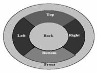
Fig 1. Sphere Map [Vallance, Calder, 2003]
5. Stereoscopic Camera
In stereoscopic camera model, an image for left eye and an image for right eye are generated separately. Image for the left eye is displayed on the right side and image for the right eye is displayed on the left side.
The view points for the two images are displaced by the distance approximately equal to the twice of InterOcular distance. The InterOcular distance will be approximately equal to 0.035 meters or 3.5 cm [Eve, 2002]. So the distance between viewpoints for the two images are displaced by 7cm which is approximately equivalent to 0.02 units in world coordinates. The scale that has been assumed is 0.003 units in world coordinates for 1cm.
The rendering of the images for both eyes is as depicted below, it uses the horizontal negative parallax which gives the illusion that the image being projected is in front of the projection plane which will be useful in providing immersion [Bourke, 1999].
Fig 2.Stereoscopic projection [Bourke, 1999]. Fig 3.Stereoscopic cameras [Bourke, 1999]
The images are being displayed in two separate viewports side by side in a single window as the rendering of images are not fast enough to animate.
7. Conclusions
The report has presented a basic ray tracing algorithm along with spherical mapping technique and stereoscopic rendering method.
The scene raytraced consists of spheres stacked in the form of an equilateral pyramid and placed in a room with rectangular planes.
The phong illumination model is used for realistic looking lighting effects. The algorithm described above can be used for generating photo realistic images of scenes containing any type of objects.
8. User Guide
Ray Tracing software implemented can be controlled using the following keys.
Note: Each normal ray traced frame consumes 20sec to render. Spherical projected scene consumes 10 sec to render. Stereoscopic images consume 50sec to render. Rendering time is empirically calculated.
(Press corresponding keys to enable options)
Normal Ray Trace Image : Key T – render time 20sec – (default option)
Spherical Map : Key K – render time 10sec
(Stereoscopic image works only when ‘Normal Ray Trace’ option is enabled)
Stereoscopic image : Key U – render time 50sec
Toggle Reflections : Key R – render time 12sec
Translate spheres left : Key G – render time 20sec
Translate spheres right : Key H – render time 20sec
9. References
Bourke P, 1999, Calculating Stereo Pairs [online],
Available:http://astronomy.swin.edu.au/~pbourke/stereographics/stereorender/ [Accessed 14 Mar, 04].
Eve-ElmerPost, 2002, Eve-ElmerPost – A brief User’s manual [online], CSC Ltd. Available: http://eve.hut.fi/docs/elmerpost/ [Accessed 19 Mar, 2004].
Hill F. S, 1990, COMPUTER GRAPHICS USING OPEN GL, 2nd edition, USA: Prentice-Hall, Inc.
Power K, 2003, Graphics Notes [online], Available: http://glasnost.itcarlow.ie/~powerk/
Graphics/Notes/ [Accessed 15 Mar, 04].
Vallance S, Calder P, 2003, Inward Looking Projections [online], School of Informatics, Flinders University of South Australia. Available: http://delivery.acm.org/10.1145/10.114
5/610000/604513/p219-vallance.pdf?key1=604513&key2=1761379701&coll=portal&dl =ACM&CFID=19109714&CFTOKEN=75792431 [Accessed 18 Mar, 2004].
Weisstein E. W, 1999, Equilaterail Triangle [online], MathWorld, WolFram web resource. Available: http://mathworld.wolfram.com/PyramidalFrustum.html [Accessed 10 Mar, 04].
Weisstein E. W, 1999, Pyramidal Frustum [online], MathWorld, WolFram web resource. Available: http://mathworld.wolfram.com/PyramidalFrustum.html [Accessed 10 Mar, 04].