Report On
Design and
Implementation Of
Computer Game
- Virtual Hockey
Outline of Report
1. Description of problems to be solved
2. Collision Detection Technique
2.1 Collision between Puck and Flipper
2.2 Collision between Puck and Wall
2.3 Collision between Puck and Puck
3. Collision Response Technique
3.1 Response for Collision between Puck and Flipper
3.2 Response for Collision between Puck and Wall
3.3 Response for Collision between Puck and Puck.
4. Physics for Puck and flipper
5. Application of Law of Momentum and Angular Impulse
6. Calculation of Spin Direction
7. Simulation loop
8. User Interface
9. Goal Detection and Scoring
10. Multiple Camera Positions
11. User Guide
12. Conclusions
13. References
14. Sample Grab
1.
Description of Problems to be solved
The problem is to model a game of Hockey which can be played by two players. This game is to simulate an executive toy “Turbo Action Hockey” by E&B Giftware, Inc. The model simulates a portable form of original Hockey game i.e. users will be provided with flippers instead of bats which they can use to hit a puck. Flippers rotate with reference to a fixed point and have variable angular velocity.
User hits a puck with certain velocity and puck should respond to the collisions with walls and flippers by changing its direction and speed. During the motion of puck it should take into account, the friction acting upon it due to hockey board and the drag due to, air resisting the motion of puck. Puck should take into account the direction of spin and its angular velocity.
One player will be the user having control over his two flippers and the other player being the computer having control over its two flippers. Computer and as well as user should be scored according to the goals they made against each other. First contestant gaining five goals should be declared Win. The interface between the Virtual Environment and user should be intuitive.
The problems above can be solved and an effective Virtual Hockey game can be modeled. Different techniques and algorithms used for solving the above problems are described below.
2. Collision Detection Technique
Standard vector mathematics formula is used to check the collisions between puck and flipper, puck and wall. The scenario is depicted below along with the formulae [David E, 1999].
The following construction applies in any dimension, not just in 3D.

Let the test point be P. A line is parameterized as L (t) = B + t * M where B is a point on the line, M is the line direction, and t € [0, 1]. A line segment is restricted with t € [0, 1]. The end points of the line segment are B and B + M.
The closest point on the line to P is the projection of P onto the line, Q = B + t * M, where t = M · (P − B) / (M · M)
The distance from P to the line is D = | P − (B + t * M) |
If t0<0, then the closest point on the ray to P is B. For t0 > 0, the projection B + t * M is the closest point. The distance D from P to the line segment is
| P − B |, for t <= 0
| P − (B + t * M) |, for 0 < t < 1
| P − (B + M) |, for t >= 1
Its usage for detecting collisions between puck and flipper, puck and wall are as described below.
2.1 Collision between puck and flipper
The formula described above is used for calculating the distance between center point of puck and sides of flipper. Center point of puck is analogous to P and line B + t * M is analogous to the side of flipper. The curved edge of flipper is considered by taking the chord joining center point of curve and two parallel points on either side of center point, which are exactly horizontal.
If the distance between center of puck and flipper is less than or equal to radius of puck, flipper and puck are collided. Collision response is described later in section 3.1.
2.2 Collision between puck and wall
The same formula described in section 2 is used for detecting collisions between puck and wall of hockey board. Point P in formula is analogous to center point of puck and line B + t * M is analogous to the line joining left and right corners of board. Front left and front right points describe line of front wall while back left and back right points describe line of back wall on the hockey board.
If the distance between center point of puck and line considered is less than or equal to radius of puck a collision has occurred and appropriate collision response is performed which is described later in section 3.2.
2.3 Collision between puck and puck
Collision Detection between puck and puck is somewhat similar to the technique described in section 2 but instead of a line segment another point is used. The technique is described below.
Consider any two pucks and their center points as A and B. Distance between these two points is given by the formula | A – B |. If the distance becomes less than or equal to sum of radius of two pucks collision has occurred between them and appropriate collision response is performed which is described in section 3.3.
3. Collision Response Technique
Standard light reflection formula is used to respond to collisions between flipper and puck and puck and walls. Same technique but with slight variations is used for collisions between puck and puck. The technique is as described below [Hill F.S, 1990].
The figure below depicts the reflection of a ray after hitting a surface.

Plane
If a ray ‘a’ is hitting a surface of normal N then the resultant ray ‘r’ is given by the formula r = a – 2 * (a . N1) * N1, where N1 is the unit vector of normal ‘N’. Here ‘a’ is the direction of ray hitting the surface and ‘r’ is the resultant direction. By figure we can imply that angle of incidence is equal to the angle of reflection.
3.1. Response for collision between puck and flipper
After detecting collisions between puck and flipper using technique described in section 2.1 Collision Response technique described above is used to retreat collision. Incident ray ‘a’ is the vector defining the direction of puck. Normal ‘N’ and plane indicate normal perpendicular to the side face of flipper and flipper respectively. Reflected direction of puck after hitting the plane of flipper is given by r = a – 2 * (a . N1) * N1 and r is the reflected direction of puck.
When flipper is in motion both plane and normal ‘N’ of flipper are rotated using rotation matrices and are used in performing calculations. Velocity and momentum are described later in the sections 4 and 5 respectively.
3.2. Response for collision between puck and wall of hockey board
After detecting collision
between puck and wall using technique described in section 2.2 Collision
response technique described above in section 3 is used to retreat collisions.
Now, the plane with which puck collides is the plane describing the wall of
hockey board and normal ‘N’ is the normal direction of wall of hockey
board. Hence the reflected direction of puck after it hits the wall is given by
the equation r = a – 2 * (a .
N1) * N1,
where ‘a’ is direction of puck movement, ‘N’ is the normal of
wall and ‘r’ indicating the reflected vector. Application of law of
momentum is described later in section 5.
3.3 Response for collision between puck and
puck
The same formula described in section 3 is used for
reflections between pucks but with slight variations. Normal direction for each
flipper is calculated using their direction of movement and this normal is used
as the normal direction for finding reflected direction of its opponent puck
and vice-versa for the other puck.
If the puck A is moving in direction U1 and
puck B is moving in direction U2, normal of U1 and U2 are
calculated. Let they be V1 and V2 respectively. Then the
reflected direction of puck A can be derived by the equation R1= U1
– 2 * (U1 . V21)
* V21, where R1 is the reflected direction of puck A.
In the similar way reflected direction of puck B can be calculated by the
equation R2= U2 – 2 * (U2 . V11) * V11. Where V11 and V21 represent
unit normal vectors. Application of law of momentum is described later
in section 5.
4. Physics for puck and flipper
Puck on the hockey board will have linear velocity
of dS/dT in the time interval dT and an angular velocity of dOMEGA/dT
in the time interval dT. Here dS
describes change in distance and dOMEGA
describes change in angle of rotation.
Both dS and dOMEGA are governed by the resultant force acting on the
puck. Resultant force is calculated as a function of all forces acting upon
pucks which are described below.
Friction on Puck (Frp): Friction being applied by
hockey board on puck is given by the equation Fmax = MUEs * N, where MUEs is the
experimentally defined static friction coefficient and N is the normal force
acting upon puck. When force being applied on puck is more than Fmax puck starts moving at the instance puck started moving
MUEs changes to MUEk which
is experimentally defined dynamic friction coefficient. [Bourg, 2002]
Normal force N is calculated as mass times the
acceleration due to gravity which will be acting in opposite direction to the
weight of puck.
Air Drag (Ad): Ideal viscous drag is a
function of velocity and some experimentally determined drag coefficient
that is supposed take into account the surface conditions of the body along
with other properties of medium the body is moving in [Bourg, 2002].
A typical drag equation will be in the form of Fv =
- Cf * V for slow moving bodies and Fv = - Cf * V2 for fast moving objects. Cf is the drag coefficient and V is the body’s speed. Hence
the drag acting upon fast moving body is proportional to the square of its
velocity.
Force of Puck (Fp): Puck at any instance will
be having a rate of change of its displacement which is called as velocity and
integration of this velocity over the time step gives its acceleration ‘a’.
Thus, force that puck possesses at any time is given by the Newton’s second law
F = m * a [Bourg, 2002]. Where ‘m’ is the mass of puck which is assigned while
it is instantiated and ‘a’ is the acceleration of puck calculated by integrated
the velocity.
Resultant force on puck: Sum of all forces
described above gives the resultant force acting upon puck. The equation for
resultant force is RF = Fp – (Ad + Frp), where RF stands for resultant force. This RF will be
used in calculating the new rate change of displacement which governs puck’s
new position and velocity. Calculation of new position of puck is described
later in section 7 (simulation loop).
Force of flipper: Flipper in the game
designed has been assigned an initial ‘∆Ω’ and fixed time step ‘∆T’.
Flipper’s ‘∆Ω’ can be varied which varies the angular velocity,
angular acceleration and angular force of flipper. When flipper hits puck the
force with which it hits puck can be calculated by taking into account its ‘∆Ω’
which can be used to calculate angular velocity and angular velocity by
differentiation of equations with respect to time step. Finally the force can
be calculated by the Newton’s second law stated above.
5. Application of law of momentum and Angular
Impulse
Law of momentum with linear velocities and law of
angular impulse both are used for collision response between two pucks and for
collision response between puck and flipper.
Collision response analysis relies on another
fundamental principle: Newton’s principle of conservation of momentum, which
states that when a system of rigid bodies collide,
momentum is conserved [Bourg, 2002]. The equation governing law of momentum is
as given below.
m1u1 + m2v1 = m1u2 + m2v2
Here, m1 refers to mass of puck and m2 refers to
mass of flipper with u1, u2 and v1, v2 corresponding to the initial and final
velocities of puck and flipper respectively. In the game the initial and final
velocity of flipper are considered to be equal assuming that velocity of
flipper is constant during its action and it can only be changed while it is at
still-stand position.
Angular Impulse: For simulating
arbitrarily shaped rigid bodies we need a general approach for calculating
physics between colliding objects. We have to apply formulas to calculate
actual impulse between colliding objects which governs the velocity of moving
body [Bourg, 2002].
We can calculate change in angular velocities of
colliding pucks using the equation stated below.
ωnew = ωold + (r1 X jN) / Icg
Where ωold is
the current angular velocity of puck and ωnew is the new angular velocity of puck. Here
r1 stands for puck radial direction and N is the unit vector
which was calculated during the calculation of reflected directions due to
collisions between two pucks. Icg stands for
mass momentum but it was considered as linear momentum of puck as calculation
of mass momentum of puck seemed tedious. Finally ‘j’ stands for ‘Impulse’ which
is given by the equation
j = -Vr (e + 1) / (1/m1 + 1/m2) [Bourg, 2002].
Here ‘Vr’ stands for
relative velocities between two objects and ‘e’ stands for ‘Restitution’.
Vr = (U1 – V1)
Where U1 and V1 are initial velocities of two
objects: puck and puck or puck and wall and the ‘Restitution’ is given by the
equation
e
= - | V1 – V2 | / | U1 – U2 |
Where U1, U2 and V1, V2 refer to initial and final
velocities of two objects either puck-puck or flipper-puck respectively.
These equations result in new angular velocity of
puck depending upon the masses of two bodies and their velocities.
6. Calculation of Spin Direction
The angular impulse equations described above guide
the angular motion of the puck which implies to spin of puck. The direction of
spin is approximated to give the effect of reality. Puck is assigned an initial
direction of rotation around y-axis (upwards) and the direction of spin after
collision is calculated using the reflected ray equation described in the
section 2. But in this case the normal of interaction is taken as the normal
vector of body facing puck and the X component in the resultant is used
to rotate the puck around y-axis. This resulted in an approximate simulation of
rotation of puck.
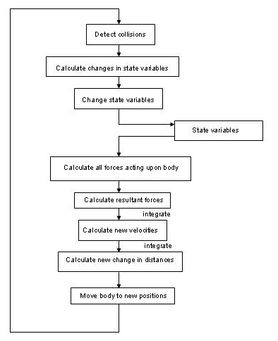
7. Simulation loop
The loop that is used in the program which calculates and updates various state variables is as shown below.
8. User Interface
An intuitive user input is provided to the game environment. User can interact through easy mouse clicks to hit the puck. A separate viewport with in the OpenGL window is provided which displays the forces of four flippers present and the score of each user.
A ‘Win’ message is displayed when a user wins. Viewport also displays information about FrameRate and the velocities with which pucks are moving.
9. Goal Detection and Scoring
As laid down as a problem to be solved, the goal detection and scoring has been incorporated into the gaming environment. If any user scores five goals against the other player he will be declared WIN and the game can be restart. When restarted scores become zero and a new game will be started.
The number of goals made by each player are displayed in a separate viewport with the game window.
10. Multiple Camera Positions
The game can be viewed from many directions. It can be viewed from puck view point. It can be viewed from player view point. The camera can be pitched and yawed to view game from different vantage points. They are easily interfaced with mouse movements associated with button clicks which will be intuitive for any user.
11. User Guide
Physics based simulation game, Virtual Hockey is user friendly and it can be controlled using following keys and mouse events.
Start Playing: Key B
Hit With Front Flipper: LEFT MOUSE BUTTON, Key 3
Hit With Back Flipper: RIGHT MOUSE BUTTON, Key 4
Introduce bonus puck: Key L
Remove bonus puck: Key M
Toggle Puck/Normal view: Key V
Preset a puck: Key P
Reset Game: Key R
Wire-Frame Model: Key N
Pitch: RIGHT MOUSE BUTTON + MOUSE MOTION
Yaw: LEFT MOUSE BUTTON + MOUSE MOTION
Move Front: Key A
Move Back: Key S
Move Up: Key Z
Move Down: Key X
Increase Flipper Force: Keys 5, 6, 7, 8 for flippers Front right, Front left, Back left, Back right respectively
Decrease Flipper Force: Keys T, Y, U, I for flippers Front right, Front left, Back left, Back right respectively
Lights On/Off Keys 1, 2, 9, 0 for red, green, blue, yellow lights respectively
Invert Colors: Key C
Toggle Full screen/Window: Key F
Exit: ESC
12. Conclusions
A physics based modeling system can be incorporated into computer games or virtual environments to enhance realism. Realism is achieved only when objects in the Virtual Environment obey physics and hence physics simulation can be declared essential for Virtual Environments.
Rigid Body simulation provides an extensive realistic imitation of real-world objects which are inherently arbitrarily shaped rigid-bodies. Basic as well as complex laws of physics are to be used depending upon the level of realism required and the complexity involved in modeling objects of different complex shapes and nature.
In order to provide the above features in the implemented Virtual Hockey Game appropriate physics laws are used in appropriate situations to simulate an executive toy “Turbo Action Hockey” by E&B Giftware, Inc.
13. References
Bourg D. M, 2002, Physics for Game Developers, 1st edition, USA: O’Reilly & Associates, Inc.
Eberly D, 1999, Distance Between Point and Line, Ray, or Line Segment [online], Magic Software, Inc. Available: http://www.magic-software.com/Distance.html [Accessed 26 Jan, 2004].
Hill F. S, 1990, COMPUTER GRAPHICS USING OPEN GL, 2nd edition, USA: Prentice-Hall, Inc.
Watt A, 1993, 3D computer Graphics, 2nd edition, USA: Addison-Wesley, Inc.
Wehner C. D, 2002, Spin-Orbit Duality, Astromechanics and Anti-Gravity [online], Available: http://wehner.org/agrav/ [Accessed 26 Jan, 2004].
Weisstein E. W, 1988, Drag Coefficient [online], WOLFRAM RESEARCH, Available: http://scienceworld.wolfram.com/physics/DragCoefficient.html [Accessed 26 Jan, 2004].
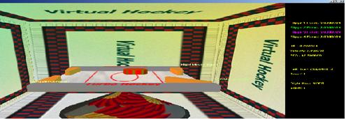
14. Screen Grab